The Mac mini will be mounted in the stereo opening. A standard DIN stereo opening is 7"x2". The Mac min is 6.5"x2". The LCD display mounting plate will be attached inside the pocket bellow the stereo opening (Mac mini opening).
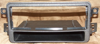
This is the old stereo sounting kit I removed. It is not quite as sturdy as the newer kit.
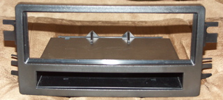
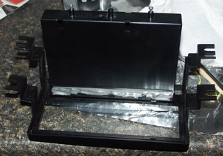
This is the new stereo mounting kit that will house the Mac mini and LCD display. It is manufactured by Scosche.
I epoxied the top and bottom of the pocket in the mounting kit. This may not have been needed, but it can't hurt....
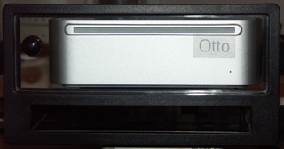
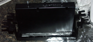
The Mac mini is sitting in the new mounting kit, behind a piece of Plexi-glass that a friend of mine cut (David Wright). The button on the left of the Mac mini is the remote power button for the Mac mini.
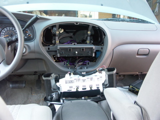
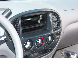
Here's the front controls removed from the dash. I have to do this to gain better access for installing the Mac mini and other items.
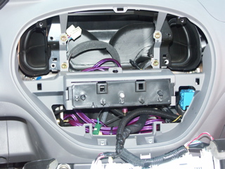
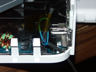
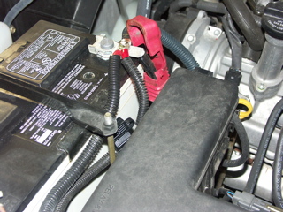
This is a close-up of the dash opening, without the stereo mounting kit. The purple cables run to an Alpine Amp beneath the passenger seat. The green & yellow connectors are for an XM Radio antenna. I will be removing the old antenna, and replacing it with a newer, smaller antenna, with one wire/connector. The wire loom tubing that appears empty, has the amplifier remote turn-on lead. It needs 12v, .5A, to make the amplifier turn on. This will be connected to the factory radio switched power. The amplifier will be on, if the key is in the on or accessory position.
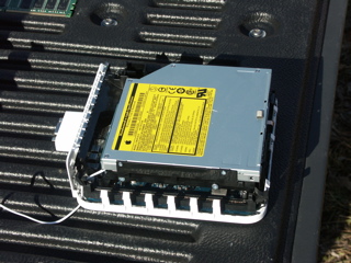
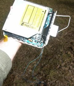
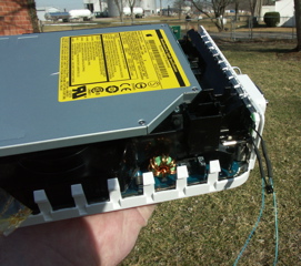
Here's the Mac mini, naked, without it's cover and DIMM. It's the 1.42Ghz version, with the 80GB HD. You can see the temperature probe at the bottom left corner of the picture.
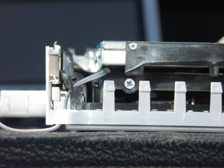
This is a close-up of the temperature probe to monitor the HD temperature.
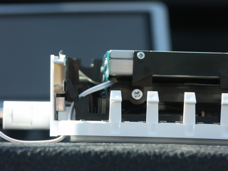
An even clearer close-up of the temperature probe. I had to remove the optical drive to lay the probe on the rear of the HD.
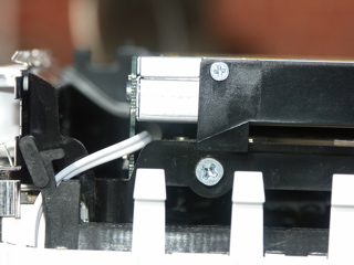
The temperature probe fits nicely between the Optical Drive & the HD. It is not snug. It should provide pretty accurate temperatures of the HD. The SMART ability of the HD provides internal HD temperatures. I'll use SMART readings to check the calibration of the probe.
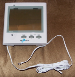
This is the Temperature display that the probe was removed from. After the Mac mini is installed in the dash, I will have quick-disconnect connectors on the probe and connect it to the Display. The "Outdoor" temperature on the display will be the temperature of the probe in the Mac mini. The temperature probe is extremely sensitive to temperature changes. It can change several times per minute.
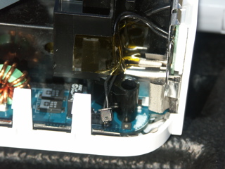
This is a close-up of of the wire/connector to the Mac mini's power switch on the back of the Mac mini.
I cut the power wire and spliced in some 30 gauge wire-wrap wire for a remote power switch.
A closer view of the splice and heat-shrink tubing.

This is an extreme close-up. You can see some melting on the connector. I originally tried to solder the blue wire into the connector. That didn't work..... That's why I cut the wire and spliced it.
Here's the power wire reconnected. It's taped back in place. The remote power switch wire has been looped as a strain relief. I also put heat-shrink tubing on the remaining length of the remote power switch wire.
Hear you can see the remote power switch wire and the temperature probe wire.
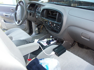
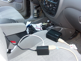
This is the power connection for my first tests. The LCD display is plugged into the left power outlet. A Fellowes 150w Inverter is plugged into the right power outlet. The Mac mini is connected to the Inverter. Both the Inverter and the power for the LCD will be hard wired to a switch on the dash.

This is the Mac mini, the LCD & an Apple Bluetooth wireless keyboard. They're running fine off the Inverter. You can see the blue remote power switch wire laying in the floor....

This shows the blue remote power switch wire, before it was shrink wrapped.

The two (2) ends of the blue wire act as the power button when touched to each other. Eventually they'll have a momentary switch connected to them.
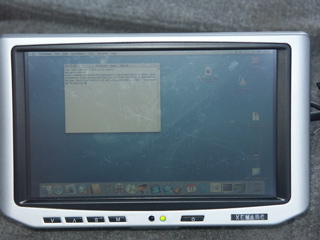
This is a close-up of the LCD display. It's a Xenarc 700TSV. The screen is touch-sensitive. It has a VGA in, two (2) A/V inputs, and a built in speaker. It comes with an IR remote. It has a USB cable that presents the touch sensitive display to the Mac mini as a mouse. The display is 800x480. It will accept inputs of up to 1600x1200, and display them. This picture is of a 1024x768 input. My son is trying out the keyboard in a terminal window. The marks on the display wipe off. They are from finger nails & plastic styli being used on the display.
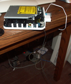
Now we're ready for a power test with all the peripherals. An extension cord is used so I can plug in the brick for a 7-port USB hub, along with the Mac mini.....
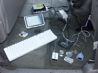
Here's all the peripherals laying in the back floorboard. The inverter isn't even getting warm....
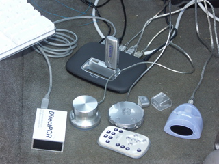
The USB hub is a Belkin 7-port hub with their new "Tetra" technology. It allows full 12Mb for each USB 1.1 device. Plugged into it from left to right are: Power, DirectPCR (XM Radio), Xenarc 700TSV Touch Sensitive Display, Griffin Technologies iMic, Keyspan Digital Media Remote IR receiver, Griffin Technologies Powermate Knob, Mini-USB connection back to the Mac mini, & a Netgear MA111v1 802.11b Adapter on the top.
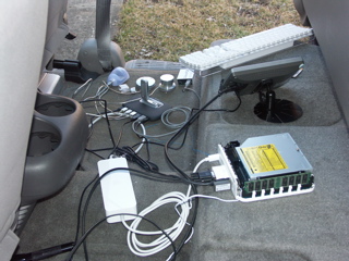
This is a view of the system and peripherals from the other side. Attached to the Mac mini's USB ports are a Dlink DBT-120 Bluetooth adapter and the cable to the Belkin USB hub. You can see the base for the LCD display. It will be attached in the pocket below where the Mac mini is mounted.

Here it is - all working and in action. I'm logged into my server at home in the back terminal window. The front terminal window shows 'rsync' being used to synchronize the Mac mini's iTunes Library with the library on our server. This is being done via the wireless connection.
I've installed a new 10 guage power line for the inverters, the LCD & the XM Radio. It's fused for 30A.